|
ST公司的STEVAL-IHM030V1演示板是基于STM8S MCU的24V高達(dá)2kW的有刷DC馬達(dá)驅(qū)動(dòng)演示套件,包括控制板和電源板.具有可配置的PI閉環(huán)速度回路,馬達(dá)指令和PI參數(shù)信息通過CAN總線,H橋拓?fù)?電流和電壓通過總線監(jiān)測,編程和調(diào)試功能,主要用在馬達(dá)牽引系統(tǒng).本文介紹了STM8S系列產(chǎn)品主要特性,方框圖以及STEVAL-IHM030V1 演示板主要特性,控制板和電源板電路圖,材料清單于PCB元件布局圖. 24 V, up to 2 kW brushed DC motor drive demonstration kit based on the STM8S microcontroller The STM8S903K3 and STM8S903F3 8-bit microcontrollers offer 8 Kbytes Flash program memory, plus integrated true data EEPROM. The STM8S microcontroller family reference manual (RM0016) refers to devices in this family as low-density. They provide the following benefits: performance, robustness, and reduced system cost. Device performance and robustness are ensured by advanced core and peripherals made in a state-of-the art technology, a 16 MHz clock frequency, robust I/Os, independent watchdogs with separate clock source, and a clock security system. The system cost is reduced thanks to an integrated true data EEPROM for up to 300 kwrite/erase cycles and a high system integration level with internal clock oscillators, watchdog and brown-out reset. STM8S主要特性: Core • 16 MHz advanced STM8 core with Harvard architecture and 3-stage pipeline • Extended instruction set Memories • Program memory: 8 Kbytes Flash; data retention 20 years at 55 °C after 10 kcycles • Data memory: 640 bytes true data EEPROM; endurance 300 kcycles • RAM: 1 Kbytes Clock, reset and supply management • 2.95 to 5.5 V operating voltage • Flexible clock control, 4 master clock sources: - Low power crystal resonator oscillator - External clock input - Internal, user-trimmable 16 MHz RC - Internal low power 128 kHz RC • Clock security system with clock monitor • Power management: - Low power modes (wait, active-halt, halt) - Switch-off peripheral clocks individually • Permanently active, low consumption power-on and power-down reset Interrupt management • Nested interrupt controller with 32 interrupts • Up to 28 external interrupts on 7 vectors Timers • Advanced control timer: 16-bit, 4 CAPCOM channels, 3 complementary outputs, dead-time insertion and flexible synchronization • 16-bit general purpose timer, with 3 CAPCOM channels (IC, OC or PWM) • 8-bit basic timer with 8-bit prescaler • Auto wakeup timer • Window and independent watchdog timers Communications interfaces • UART with clock output for synchronous operation, Smartcard, IrDA, LIN master mode • SPI interface up to 8 Mbit/s • I2C interface up to 400 Kbit/s Analog to digital converter (ADC) • 10-bit, ±1 LSB ADC with up to 7 muxed channels + 1 internal channel, scan mode and analog watchdog • Internal reference voltage measurement I/Os • Up to 28 I/Os on a 32-pin package including 21 high sink outputs • Highly robust I/O design, immune against current Injection Development support • Embedded single wire interface module (SWIM)for fast on-chip programming and non intrusive Debugging 
圖1.STM8S方框圖 STM8 CPU核 Central processing unit STM8 The 8-bit STM8 core is designed for code efficiency and performance. It contains 6 internal registers which are directly addressable in each execution context, 20 addressing modes including indexed indirect and relative addressing and 80 instructions. Architecture and registers • Harvard architecture • 3-stage pipeline • 32-bit wide program memory bus - single cycle fetching for most instructions • X and Y 16-bit index registers - enabling indexed addressing modes with or without offset and read-modify-write type data manipulations • 8-bit accumulator • 24-bit program counter - 16-Mbyte linear memory space • 16-bit stack pointer - access to a 64 K-level stack • 8-bit condition code register - 7 condition flags for the result of the last instruction Addressing • 20 addressing modes • Indexed indirect addressing mode for look-up tables located anywhere in the address space • Stack pointer relative addressing mode for local variables and parameter passing Instruction set • 80 instructions with 2-byte average instruction size • Standard data movement and logic/arithmetic functions • 8-bit by 8-bit multiplication • 16-bit by 8-bit and 16-bit by 16-bit division • Bit manipulation • Data transfer between stack and accumulator (push/pop) with direct stack access • Data transfer using the X and Y registers or direct memory-to-memory transfers The STEVAL-IHM030V1 is brushed DC motor (BDC) demonstration kit which provides a platform to introduce users to a 24 V, up to 2 kW brushed DC motor drive. A typical use for the kit is in traction system applications. The kit contains two stacked modular boards: a power stage board and a control board. It represents a compact solution and provides efficient power dissipation due to the mounting of the power MOSFET on a dedicated IMS layer. This document describes the features of the STEVAL-IHM030V1, provides information on its use, and explains how it performs bidirectional speed control of a brushed DC motor. The brain of the system is the STM8S 8-bit microcontroller, which drives the full H-bridge topology, implements the PI closed loop control speed, manages the encoder signal feedback using the dedicated timer peripheral and manages the commands motor and PI configuration messages through the CAN bus. In the example application described, the supported brushed DC motor is supplied by 24 V and is powered up to 2 kW.
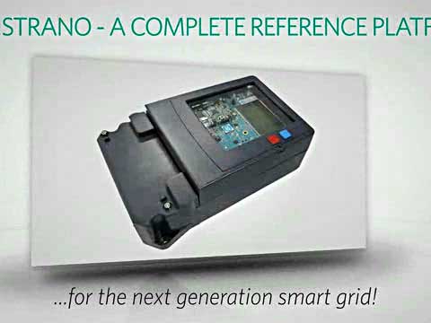
圖2.STEVAL-IHM030V1 演示板外形圖 STEVAL-IHM030V1 演示板主要特性: – Bidirectional drive for a 24 V brushed DC motor up to 2 kW – Configurable PI closed speed loop – Motor commands and PI parameter messages via CAN bus – H-bridge topology – Efficient power dissipation with power MOSFETs mounted on a dedicated IMS layer – Program and debug capability – Security functions: current and voltage bus monitoring The STEVAL-IHM030V1 demonstration kit consists of 2 separate boards: ● Control board ● Power board
圖3.STEVAL-IHM030V1 控制板和電源板框圖
圖4.STEVAL-IHM030V1 板電源部分
圖5.STEVAL-IHM030V1 開發(fā)板控制部分電路圖
圖6.STEVAL-IHM030V1 開發(fā)板電源部分電路圖 STEVAL-IHM030V1 開發(fā)板材料清單:
圖7.STEVAL-IHM030V1 開發(fā)板PCB元件布局圖(頂層)
圖8.STEVAL-IHM030V1 開發(fā)板PCB元件布局圖(底層) 詳情請見:  CD00231332[1].pdf
(1.16 MB)
CD00253554[1].pdf
(474.82 KB)
CD00231332[1].pdf
(1.16 MB)
CD00253554[1].pdf
(474.82 KB)
來源:網(wǎng)絡(luò) |